Utzon (X) 2017
Robotic Based Composite Design
Utzon Centre, Aalborg, Denmark
2017
The workshop focussed on 3D printing polymer based concrete through a 6-axis industrial robotic arm, varying the structural and thermal property of the concrete mix. In the first 2 days focus was on the fundamentals of the thermal behaviour or material and concrete & introduction to the robot. These sessions were taken by Isak Worre Foged and Mads Brath from Aalborg University.
In the following days focus was on 3D printing basics and how material behaviour and machine parameters can be hard coded using a custom software, Alice Studio. These sessions were taken by Shajay and Vishu Bhooshan from ZH | CODE. And Alice Studio is written by them. Finally a wide range of geometry and concrete mix was tried with the robot to test printability and printable concrete mix.
My particular interest was to develop a toolchain/workflow to create architectural forms. This workflow included graph base basic shape generation in Grasshopper (inspired by Shajay); export the points in a CSV file; read the CSV file in Alice Studio; modify the points based on defined operators in Alice Studio ; export the layered points in another CSV file; read the CSV file in Grasshopper and create the robot toolpath using KUKA-PRC.
Generating the Base geometry:
During the workshop, in his one of the Instagram post Shajay showed how some basic shape can be generated from a set of lines and that can be further modified into a printable geometry. I applied a logic using Grasshopper and custom python code to write the information to a CSV file.
Base Curve Generation Process | Rhino- Grasshopper
There can be n number of possibility in which one could draw the graphs, generating infinite number of possibilities.

Graph Possibilities
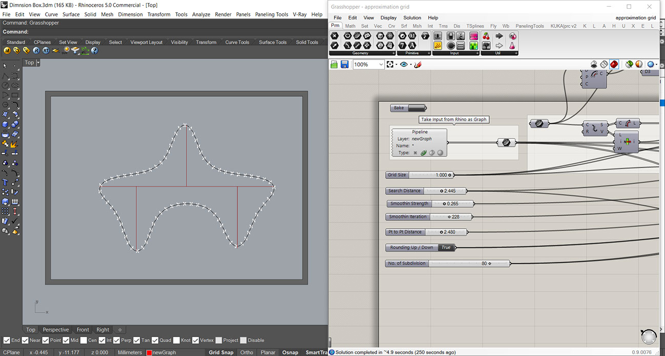
Choice of graph & final shape
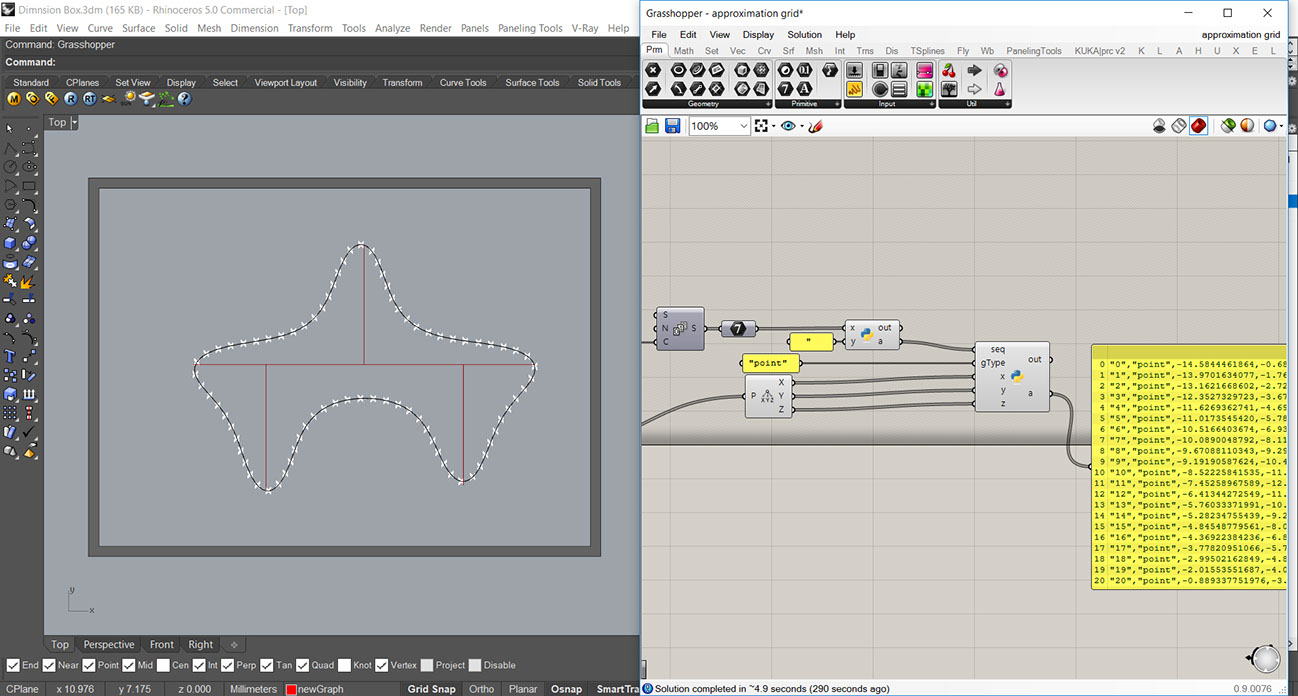
Exporting the final shape as points in a CSV file
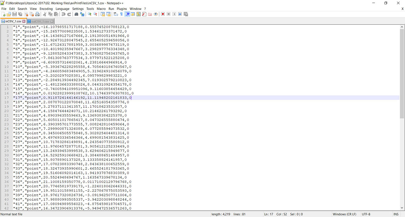
Appearance of a CSV file
Geometry Modification in Alice Studio:
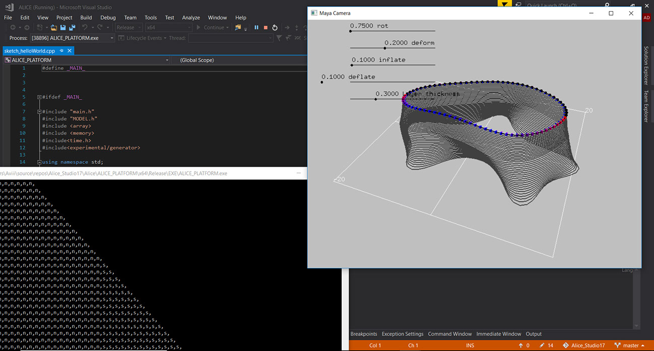
Alice studio has been designed in accordance with Model-View-Control paradigm. The basic parameters, functions, operations are written at first. Then how they will appear and finally how users can control the parameters and operations.
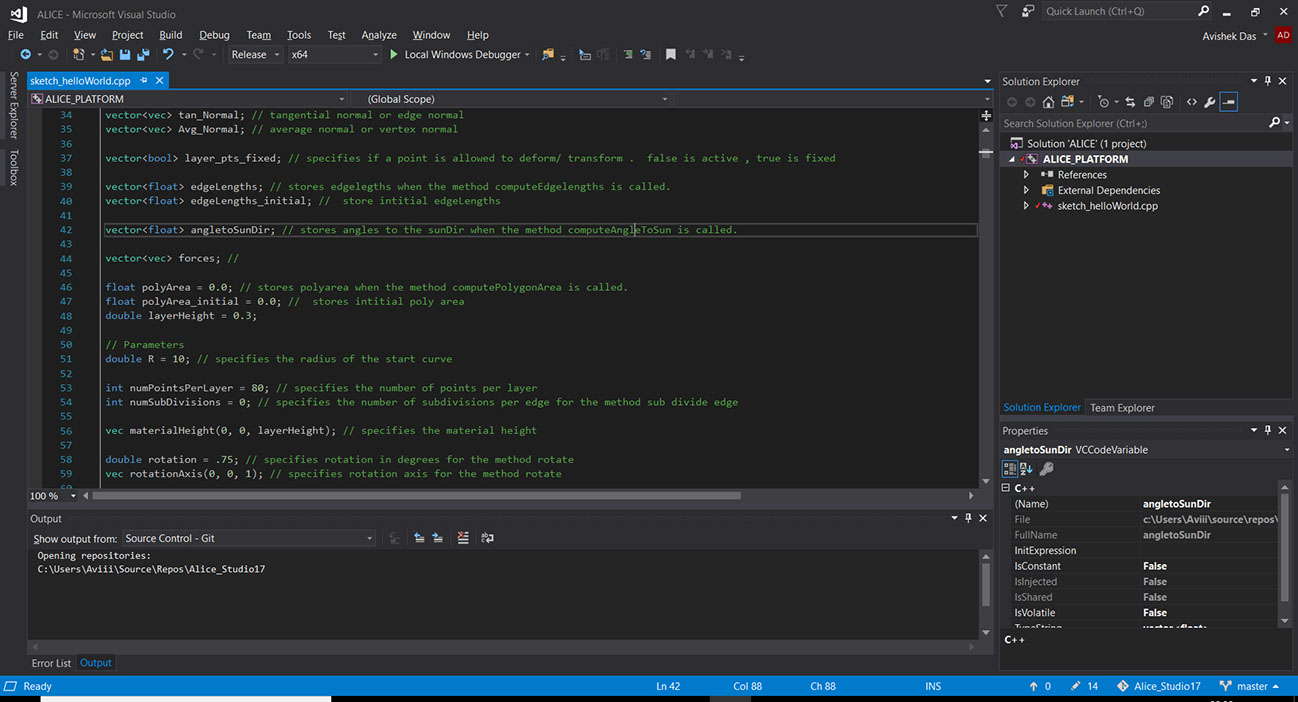
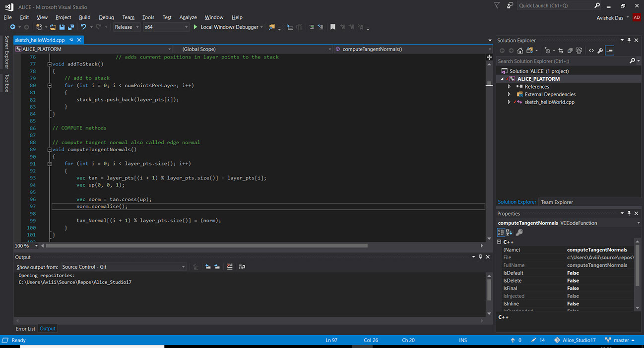
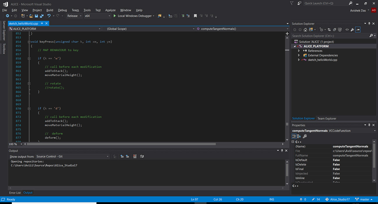
Alice Studio | Model View and Controller part in order
Initially all the modifiers were applied on a circular form. It was generated within Alice and modified using the functions written within Alice.
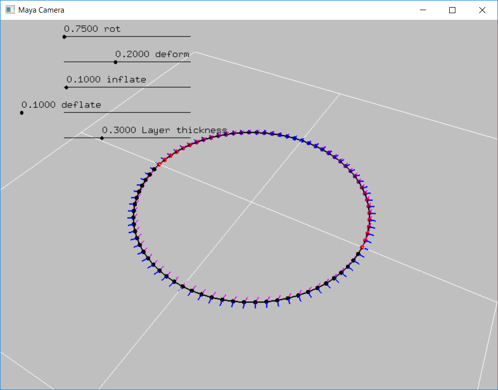
Alice Studio | Base geometry, a circle
One of the functions allowed to read the CSV and make points out of it. Then the modifiers were used.
Alice Studio | Importing Custom shapes from CSV
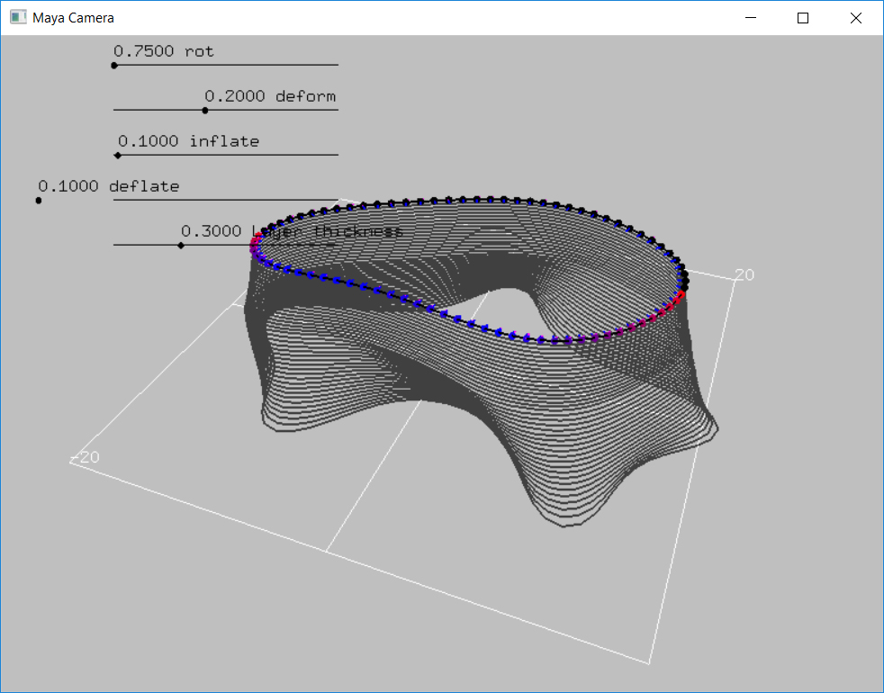
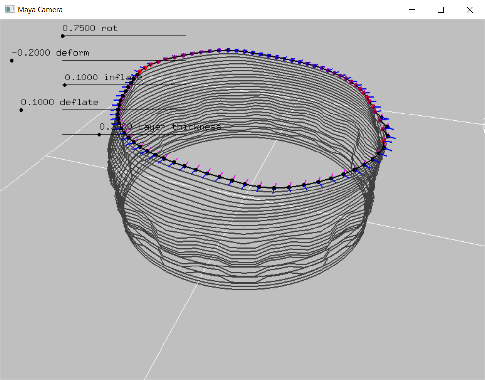
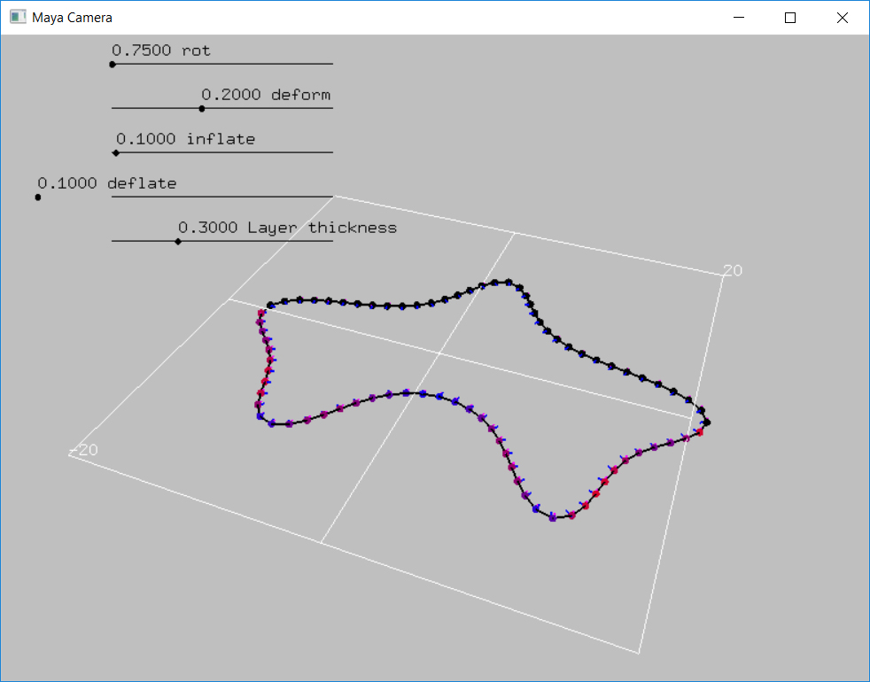
Alice Studio | Modifiers applied
Alice Studio | The key strokes associated with each shape denoted as a constructing grammar of the geometry
Next step was to export these in a simple CSV and read it in Grasshopper and create robot toolpath from it.
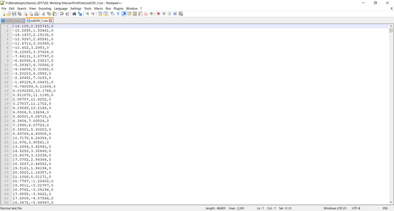
Appearance of CSV of the final geometry
The final appearance of the print was predicted using the Grasshopper. In this kind of 3D printing, final print becomes explicit property of the geometry based on the nozzle dia, layer height etc.
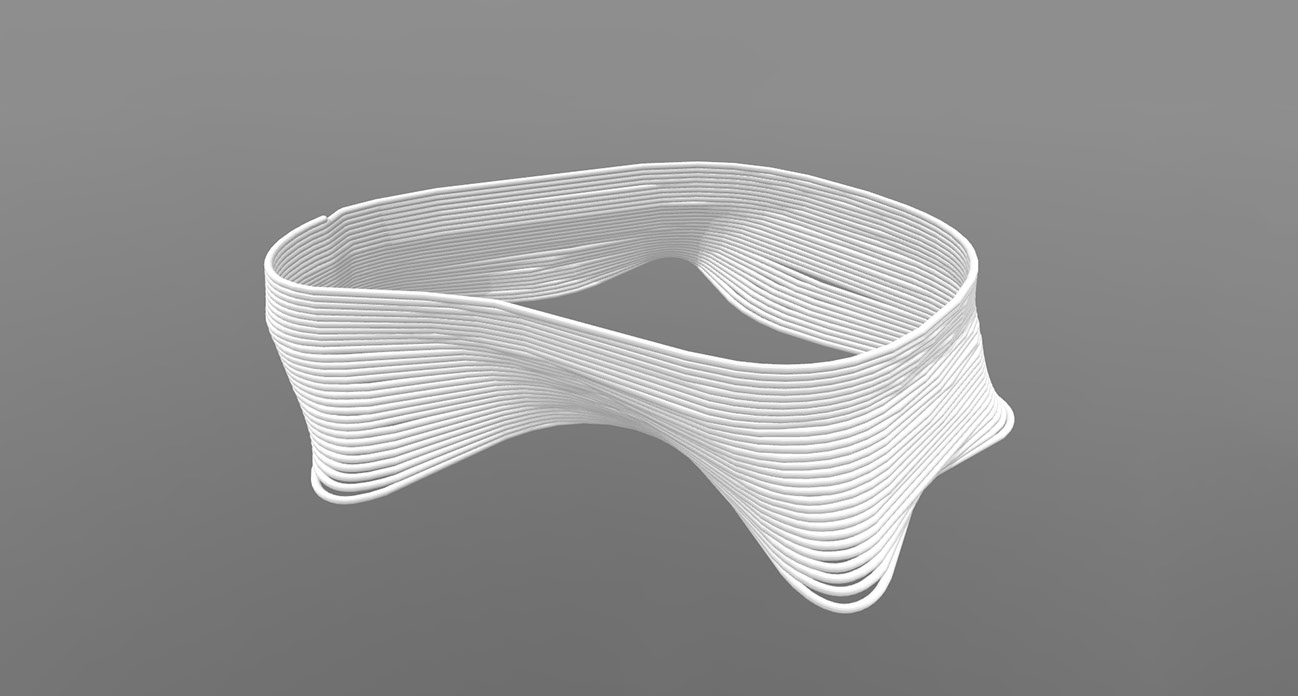
Approximate visualization of the full print
Material | Toolpath | Robot :
The next step was to prepare the material, generate the robot toolpath and run the robot and the extruder to print the geometry.
For the print the material mix we used was perfected after 32 mix batches. The mix got worked was : 4396 gm of Densite cement, 620 gm of water and 40gm of black color powder, mixed for 7 minutes in a food processor. As of the extruder, it was a RAM extruder that printed clay for Utzon(X) 2016 and the robot was KR 90 27 R2500.
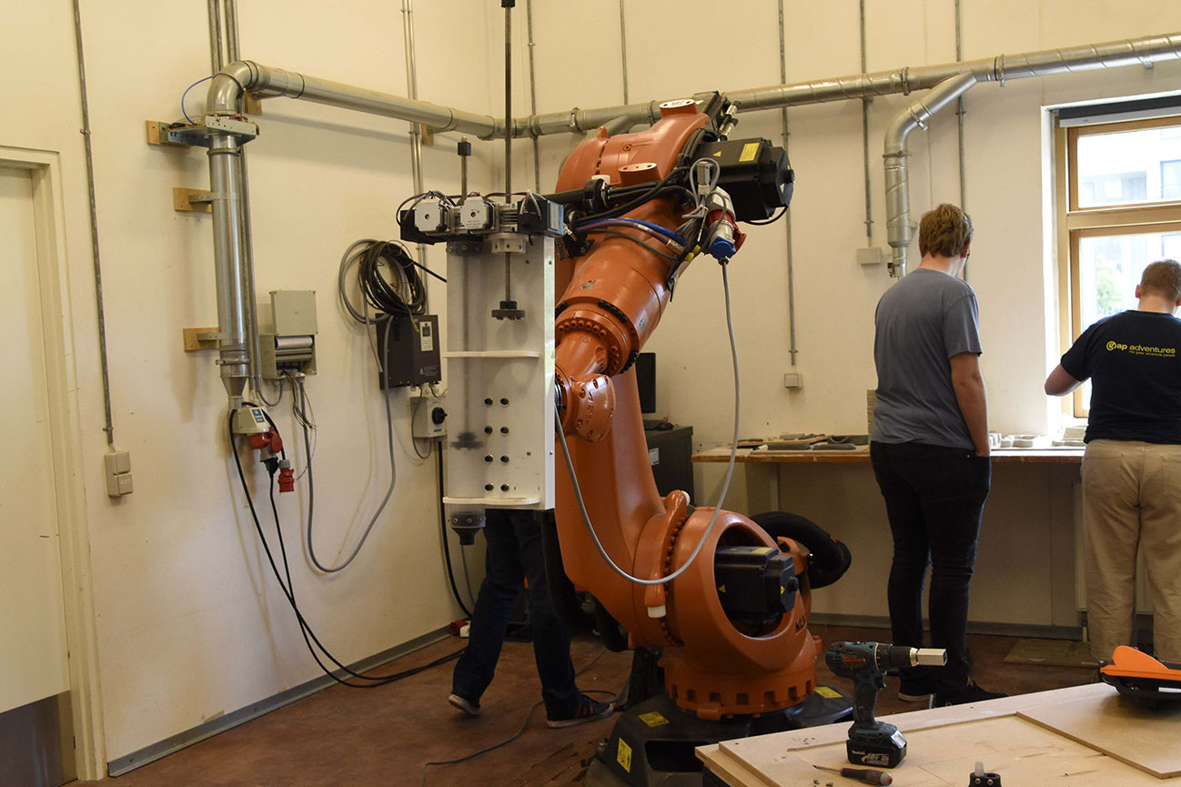
Robot and the Extruder Setup
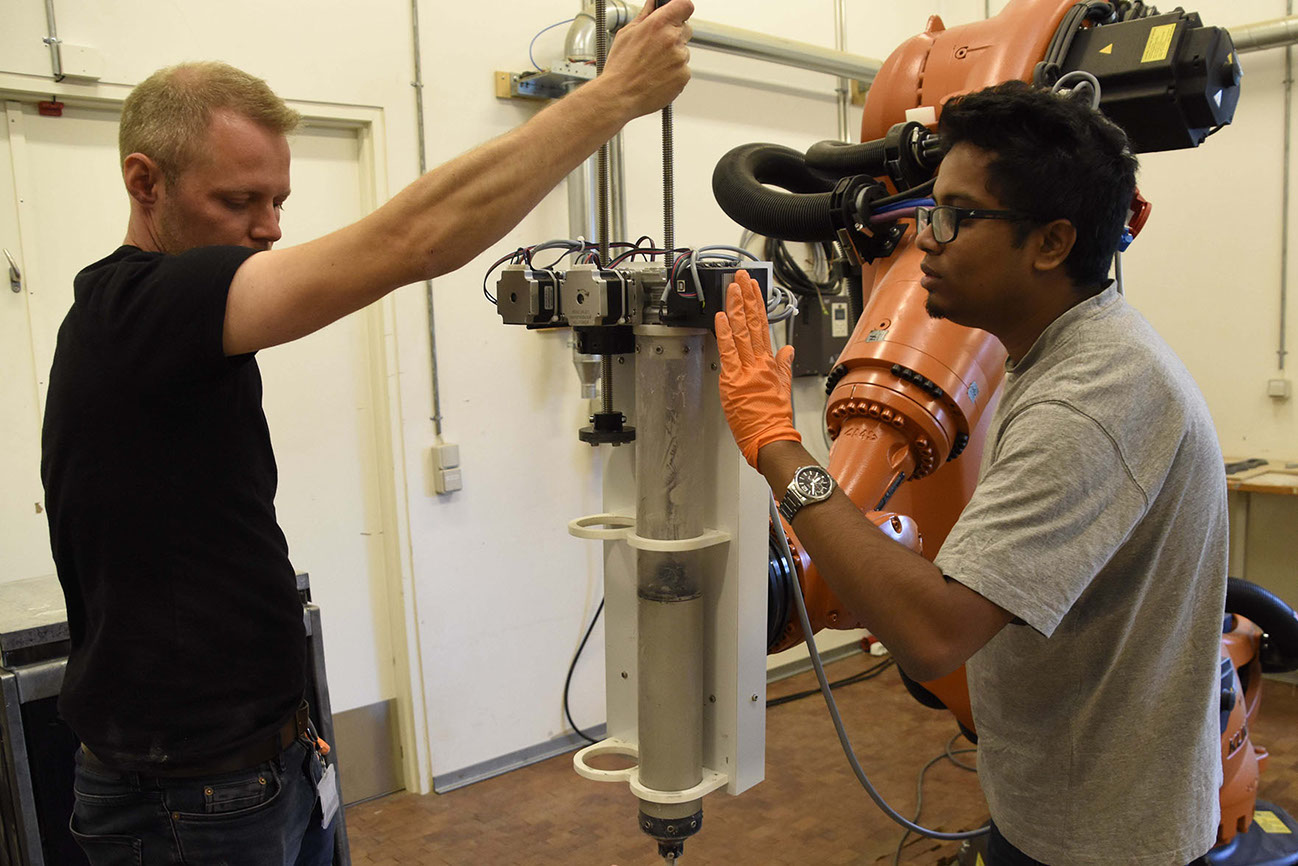
Finalizing the extruder setup with material | Mads Brath is teaching how to keep the plunger in place
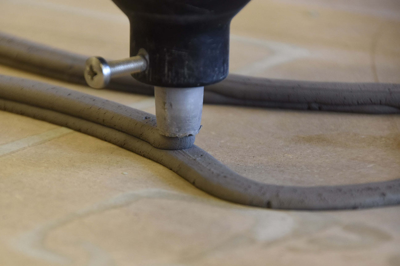
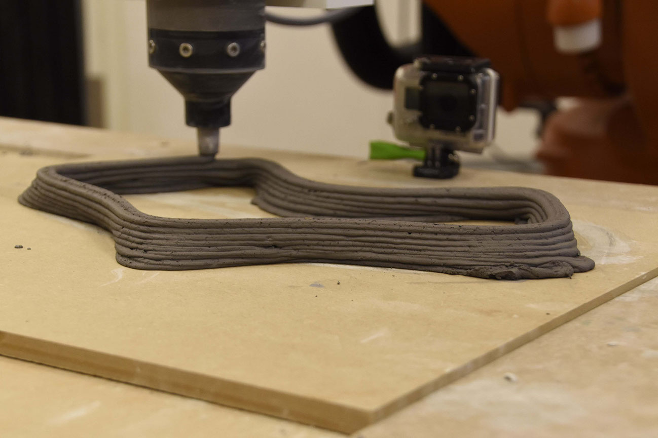
First Layer of the test print of a simple geometry
Close up look of the fresh print
Analysis of a test print on manual mode.
For the final print , I had employed a particular technique. Top and bottom most toolpath were parallel to XY plane while the internal toolpath went into a spiral. This ensured a smooth robot movement.

Toolpath Tweaking
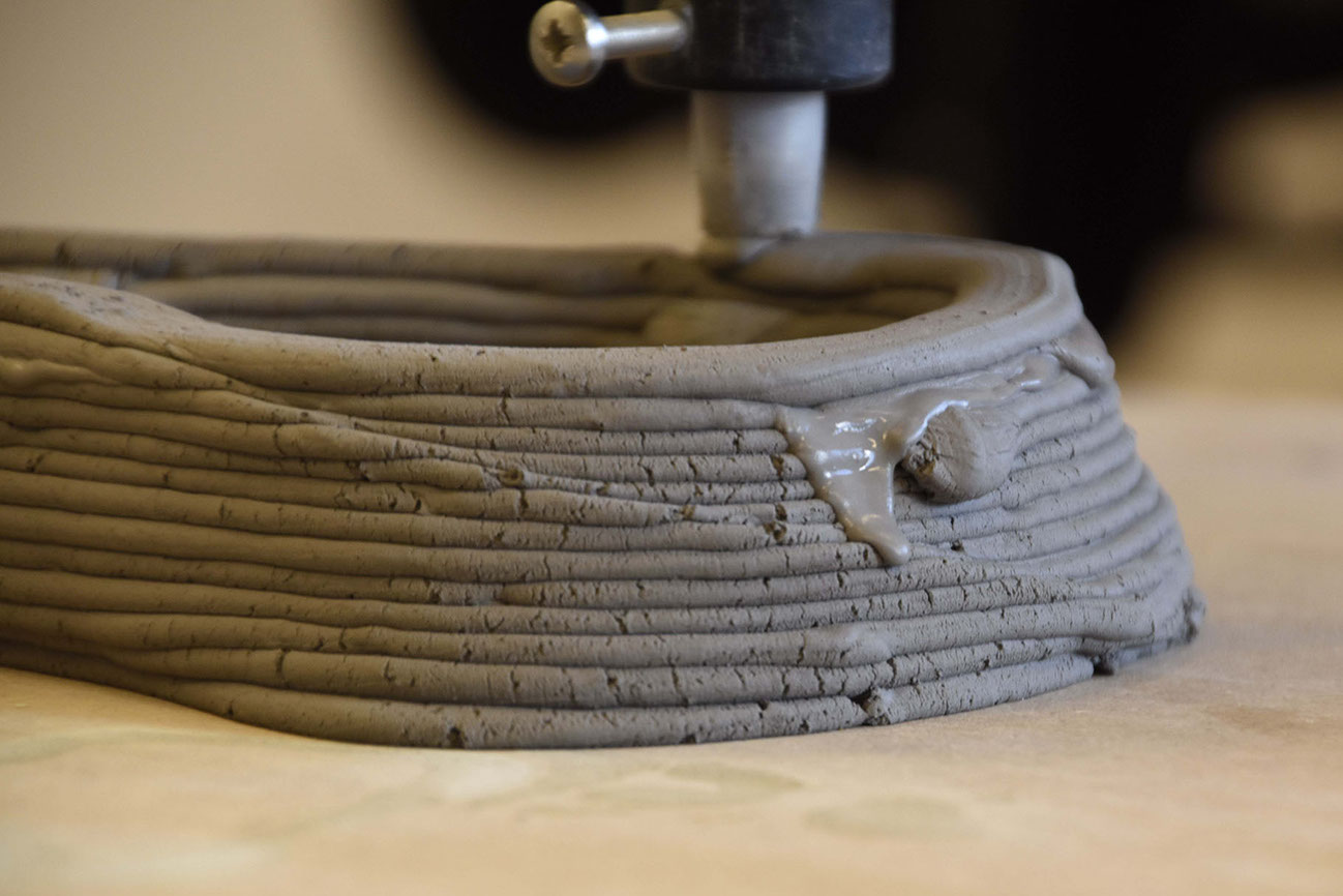
Printing the final form.
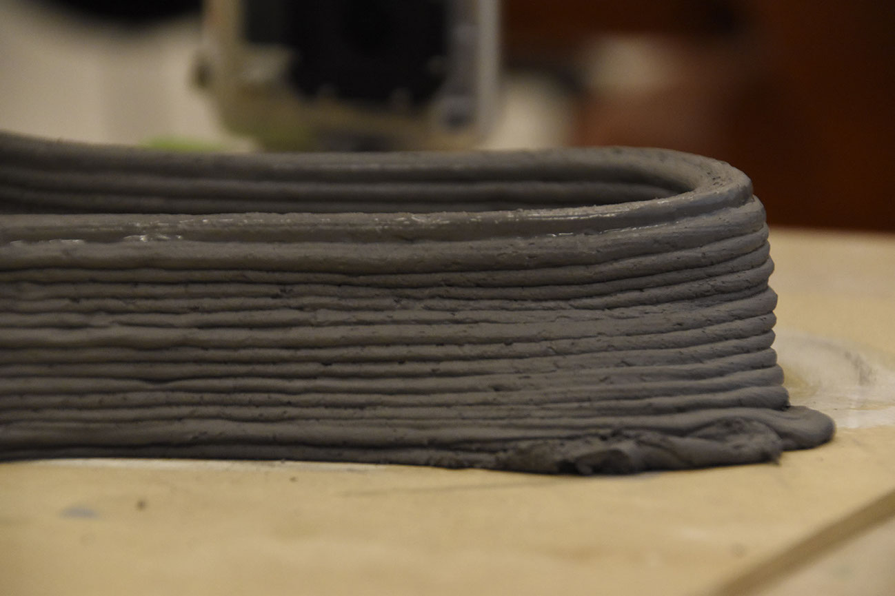
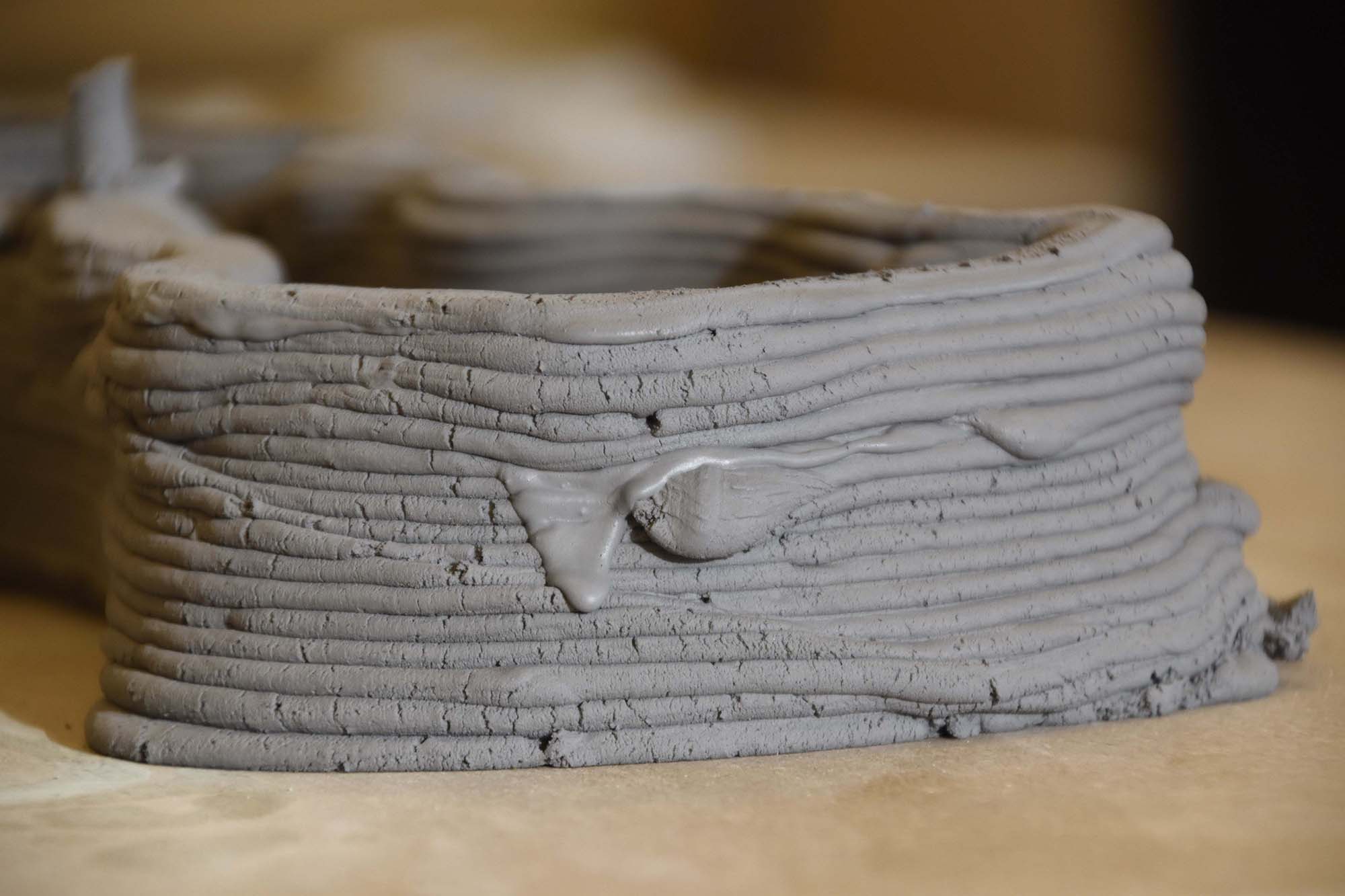
Close up of layers
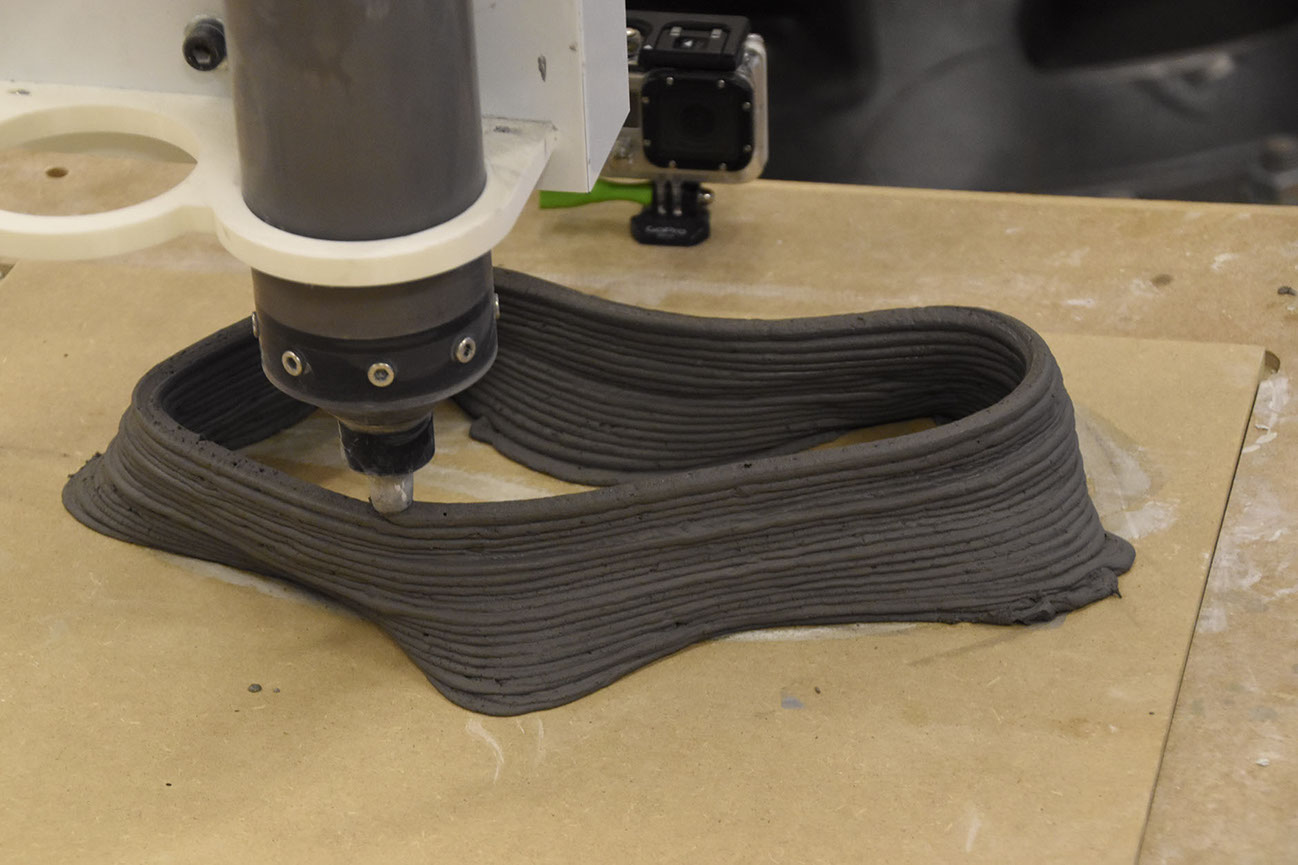
Print in midway
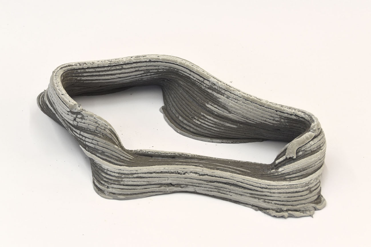
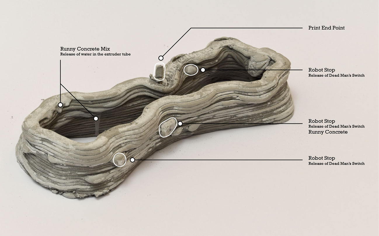
Final Print
The final print could not stand up in a particular place and fallen from there. And a salt deposition was seen in the dry region. Thus the whitish mark on the print.
The summer school process can be seen the following video.
top

avishek das | 2018